In part 1, Retrofit Single Ply Roof Systems: An Assessment of Wind Resistance, we provided information about the following:
- Four (4) methods to re-cover a metal panel roof
- The many options for attaching a single-ply system to a metal panel roof
- An example calculation for wind uplift design pressures and appropriate fastener patterns that provide the necessary resistance capacity
- Industry concerns about wind uplift when not attaching the retrofit single-ply system into every purlin
In this blog, we will discuss and analyze the four full-scale physical tests that were performed to determine their wind-uplift capacity.
Physical Testing
There have been no publically available validation studies or data supporting any particular approach to the installation of retrofit single-ply roof systems (RSPRS). Non-validated attachment methods could result in failures during wind events. Therefore, the objective of GAF’s physical testing program was to determine the wind-uplift resistance of RSPRS fastened directly into purlins. A variety of fastening patterns and fastener densities were tested in order to provide a better understanding of the effect of wind loads on these systems. The physical testing was performed at the Civil, Architectural and Environmental Engineering Department of the Missouri University of Science and Technology in Rolla, MO (MS&T).
Test Roof Construction
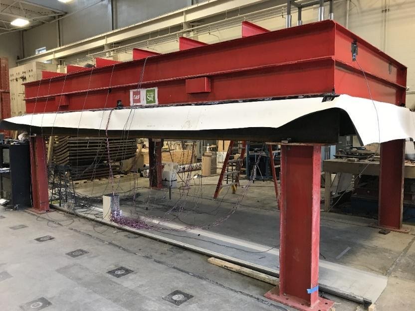
Four full-scale test roofs were constructed and tested in a 10 ft. wide x 20 ft. long chamber. The test roofs were installed by Missouri Builder Services, Jefferson City, MO, with oversight by GAF. After the test roofs were constructed, the MS&T research team instrumented the assemblies for data collection.
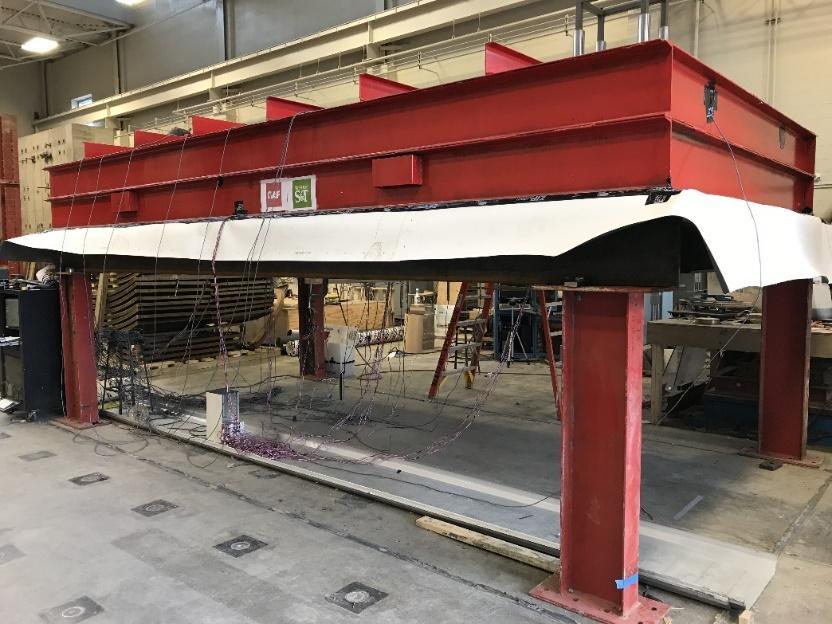
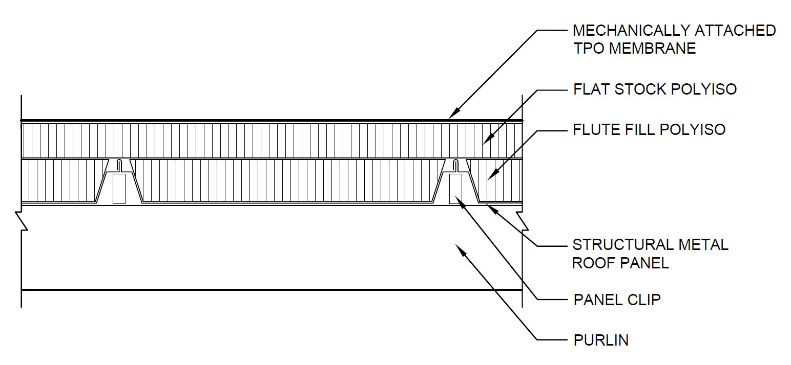
The four test roofs consisted of 24 in. wide, 24-gauge structural metal roof panels attached to 16-gauge Z-purlins with concealed expansion clips and purlin screws. The purlins were connected to and supported by horizontal steel channels; the purlin/channel construction was supported by four vertical steel columns. To complete the test specimen, flute fill polyisocyanurate insulation, flat stock polyisocyanurate insulation, and a mechanically attached 60 mil TPO membrane were installed. Prior to membrane installation, the insulation was mechanically attached with minimal fasteners to prevent shifting during the testing. The cross-section shows a graphical representation of the completed RSPRS over the structural metal panel roof system.
For Tests #1, #2, and #3, purlin fasteners and 2 3/8 in. barbed fastener plates were used to secure the membrane, simulating a “strapped” installation. The fasteners and plates were not stripped in. For Test #4, purlin fasteners and 3 in. specially-coated induction weld fastener plates were used.
The purlins in all tests were attached to C-channels. This did not allow for data collection at a purlin-to-mainframe connection. When an RSPRS is mechanically attached to every other purlin, the load path is altered significantly. This raises a question about the effect on the wind-uplift capacity of the existing metal building when the load path is altered. More information on that topic can be found here. Therefore, it is recommended to engage a structural engineer when altering the load path of an existing structure.
Results and Discussion
The table shows the ultimate loads achieved, tributary area and load per fastener, as well as fastening method. The term “ultimate load” refers to the point of failure of the roof system during physical testing.
| Test Roof # | Ultimate Loada, psf | Fastening Pattern | Tributary Area per Fastener, sf | Load per Fastener, lbs | Fastening Method |
| 1 | 162.7 | 5 ft. o.c. x 12 in. | 5 | 813.5 (800) | Above Membrane |
| 2 | 119.5 | 5 ft. o.c. x 24 in. | 10 | 1195 (1160) | Above Membrane |
| 3 | 61.9 | 5 ft. o.c. x 36 in. staggered | 15 | 928.5 (890) | Above Membrane |
| 4 | 64.8 | 5 ft. o.c. x 24 in. staggered | 10 | 648 (593) | Induction Welded |
Test #1
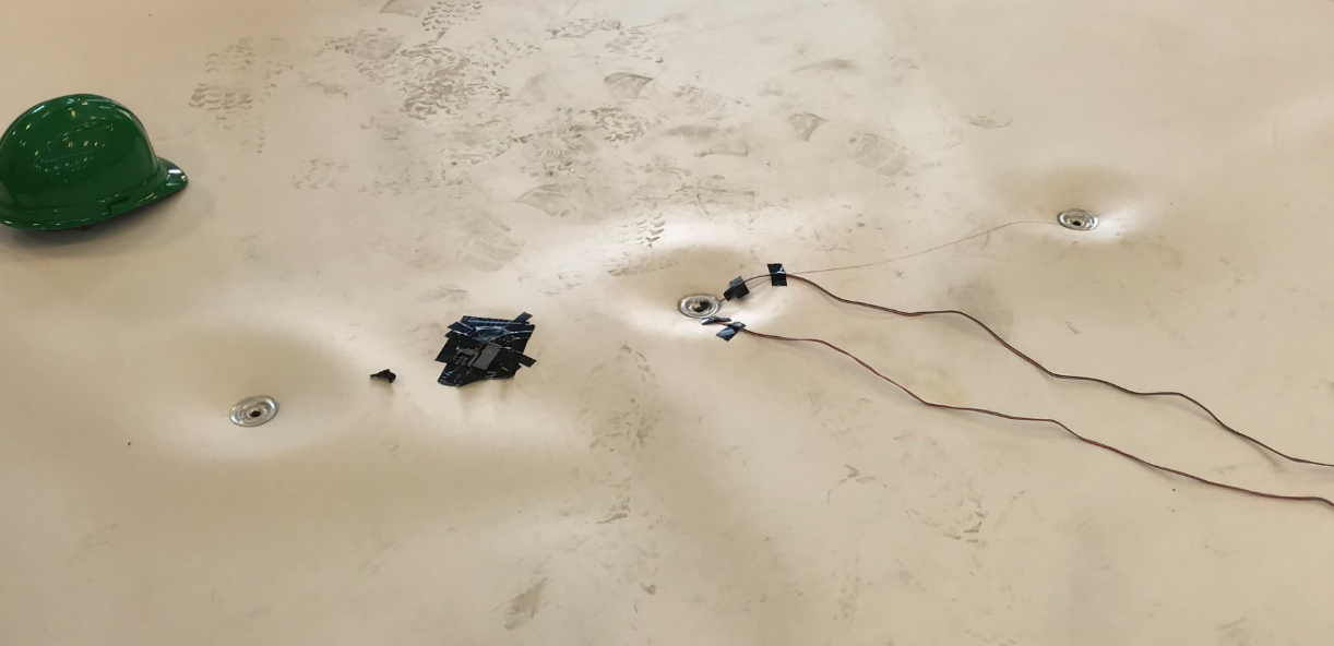
The fastening pattern for Test #1 was 5 ft. o.c. fastener rows and 12 in. fastener spacing within the row. Test #1 failed when the membrane ruptured simultaneously at seven fastener locations in the center purlin. The system successfully completed 160.1 psf and then failed as the pressure was being increased to 174.5 psf. The membrane pulled over the five center fastener plate locations in an essentially circular pattern along the outer edges of the fastener plates. The outer two failure locations resulted in L-shaped tearing of the membrane, which was attributed to the boundary conditions of the test chamber. The fastener plates were deformed upward. There were many locations of permanent upward membrane deformation.

The permanent upward membrane deformation was evident along the edges of the rows of fasteners, as can be seen in the upper row of fasteners in the photo. There was very little permanent upward membrane deformation at the centerline between fasteners within a row. This pattern of deformation leads to the belief that the load within the membrane is being transferred from fastener row to fastener row, and not significantly from fastener to fastener within a row.
Test #2
The fastening pattern for Test #2 was 5 ft. o.c. fastener rows and 24 in. fastener spacing within the row. Test #2 failed when the membrane ruptured simultaneously at the three central fastener locations in the northern quarter-point row of fasteners. The system successfully completed 116.9 psf and then failed as the pressure was being increased to 124.1 psf. The membrane pulled over the three center fastener plate locations within the row. The center rupture was circular at the fastener plate. The outer two ruptures were “D” shaped; the straight-line edges were attributed to the boundary conditions of the test chamber.
The tributary area for each fastener for Test #2 was double that of Test #1. This led to the hypothesis that the ultimate load for Test #2 would be one-half of that from Test #1, or 81.4 psf. However, the ultimate load was 119.5 psf, which is approximately 73% of that from Test #1. This is believed to indicate that the membrane transitioned from one-way loading to a more efficient two-way loading.

The load was not only distributed across the 5 ft. purlin-to-purlin span (as was the case in Test #1), but was also distributed between fasteners within a row. The uplift loads were pulling on the fastener and fastener plates from all sides (two-way loading) instead of just two sides (one-way loading). During the test, the membrane deflected up approximately 4 in. between fasteners within a row. The loads were more equally distributed within the membrane and around the fastener plate, and therefore, the load per fastener increased from 813.5 lbs. (Test #1) to 1195 lbs. (Test #2).
The membrane resisted the uplift loads in two generalized directions: between fastener rows and between fasteners within a row, which aligns with the machine direction (MD) and cross-machine direction (XMD) reinforcement yarns within the membrane, respectively. The membrane had permanent upward deformation between rows and between fasteners within a row because of this two-directional loading. The permanent upward membrane deformation was circular around fasteners.
Test #3
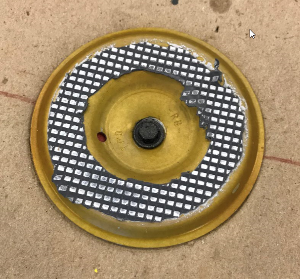
The fastening pattern for Test #3 was 5 ft. o.c. fastener rows and 36 in. fastener spacing within the row; fasteners were staggered row to row. Test #3 failed when the membrane ruptured at a single fastener location in the southern quarter-point row of fasteners. The system successfully completed 59.3 psf and then failed as the pressure was being increased to 66.5 psf. The membrane pulled over the center-most fastener plate within the row (at the red circle).

The photo shows a close up of the failure location for Test #3. The failure was “D” shaped, similar to failure locations in Test #2. The flat edge was on the boundary edge of the test roofs; the rounded edge is towards the center of the test roof.
Similar to Test #2, there was circular upward permanent membrane deformation at fastener locations for Test #3 as shown in Figure 10. This shows that the membrane is being loaded in the MD and XMD. This is due to the relatively wide spacing of the fasteners (2 ft. and 3 ft.) relative to Test #1, which had 1 ft. spacing of fasteners within a row.
The tributary area for each fastener for Test #3 was 50% greater than Test #2. This led to the hypothesis that the ultimate load would be 2/3 of Test #2, or about 79.7 psf. However, the ultimate load was 61.9 psf which is approximately 52% of that from Test #2.
Comparing Test #3 to Test #1, traditional assumptions based on tributary area would lead to an expected ultimate load for Test #3 to be 1/3 of Test #1. The ultimate load from Test #1 was 162.7 psf, so the expected ultimate load for Test #3 was 54.2 psf. The actual ultimate load for Test #3 was 61.9 psf which is approximately 38% of that from Test #1.
While two-direction membrane loading appears to increase the expected ultimate load of a roof system relative to the traditional linear expectation of failure load, it appears there is a limit to this increase. For this series of tests, the limit seems to be 5 ft. o.c. for fastener rows with 24 in. fastener spacing within each row.
Test #4
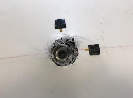
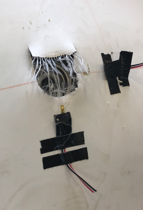
The fastening pattern for Test #4 was 5 ft. o.c. fastener rows and 24 in. fastener spacing within the row; fasteners were staggered row to row and induction welded. Test #4 failed in two locations—a fastener plate pulled over the fastener head and the membrane separated at the reinforcement layer at the adjacent welded fastener plate. The system successfully completed 59.3 psf and then failed as the pressure was being increased to 66.5 psf. The failures occurred in the southern quarter-point row of fasteners. The photo shows the 2 failure locations for Test #4.

Test #4 used induction welded fasteners, which means the fastener plates were under the membrane. Therefore, the membrane was cut in order to evaluate each failure.
Based on audible observation at the time of failure, the two failures occurred “simultaneously.” It was difficult to determine from visual examination which occurred first: the fastener plate pulling over the fastener head or the delamination of the membrane at the fastener plate.
Test #4 and Test #2 have the same tributary area per fastener location—10 square feet. However, Test #2 achieved a 119.5 psf ultimate load and Test #4 achieved a 64.8 psf ultimate load. All components were identical for both test roofs except for the fastener/plate combination and that Test #4’s fasteners were staggered row-to-row.
The above-membrane fastener (e.g., an in-seam fastener) is 2 3/8 in. in diameter. An induction welded fastener plate is 3 in. in diameter and is constructed such that a raised ‘ring’ surface adheres to the membrane, not the entire fastener plate.
The area of a standard 2 3/8 in. above-membrane fastener plate is approximately 4.4 square inches. The area of the attachment surface for an induction welded fastener plate is approximately 3.3 square inches. Therefore, an induction welded fastener plate has approximately 75% of the surface area of a traditional mechanically attached fastener plate to restrain the membrane.
Individual fastener load for Test #2 (with the same tributary area as Test # 4) was 1195 lbs. Direct extrapolation to the induction welded fastener plate (at 75%) leads to the predicted value of the fastener load for Test #4 to be 896 lbs. This prediction assumes the reinforcement is the weak link, but the test clearly shows the cap-to-core connection to be the weak link, and therefore, it makes sense that the failure load per fastener for Test #4 was less than 896 lbs. In fact, it was 648 lbs per fastener.
The analysis of these two different types of fastening methods and failure modes supports the result that Test #4 has lower wind uplift resistance than Test #2 even though the tributary area for each fastener is the same for Tests #2 and #4.
Conclusions and Recommendations
Review and analysis of the four full-scale physical tests of retrofit single-ply roof systems installed over structural metal panel roof systems resulted in a number of conclusions. They are as follows:
- Uplift resistance of RSPRS and individual fastener loads in an RSPRS are based on the membrane’s reinforcement strength and one-directional versus two-directional loading of reinforcement.
- Reducing the overall fastener density increases the tributary area for each fastener. As expected, the ultimate load is reduced with larger tributary areas.
- Two-directional membrane loading increases the expected ultimate load of a roof system relative to linear extrapolation based on fastener tributary area. However, it appears there is a limit to this expected increase. For this series of tests, the ultimate load exceeded expectations for the Test #2 fastening pattern, but the ultimate load was more in line with traditional linearly extrapolated expectations for the Test #3 fastening pattern.
- This work emphasizes the limitations of extrapolation and validates the use of physical testing to determine uplift resistance of roof systems.
- Permanent deformation of the membrane was observed in all four physical tests at the end of testing and was not seen to be a water-tightness issue. The test procedure performed did not determine what pressure during the test cycling the membrane deformation began. This observation may provide an explanation for “wrinkles” observed in mechanically attached membranes that have experienced high wind events.
For additional information about this topic, here is the GAF paper that was presented at the 2020 IIBEC Convention and Trade Show, and here is a webinar presented in early 2020.
The post Retrofit Single Ply Roof Systems: Physical Testing appeared first on GAF Blog.