By Brian Nelson, Owner, Nelson Mechanical
Nelson Mechanical Design is the largest mechanical contractor on the island of Martha’s Vineyard. We have 20 techs in the field that install and service plumbing and HVAC systems ranging from mini-splits to geothermal to water treatment to solar.
We really enjoy “rescue” projects in which we get challenged to figure out why systems don’t work and how to make them work.
Underground Geothermal Leak
They left after the summer season and asked us to develop a rescue plan to find and repair the geothermal underground leak. The geothermal wells were connected underground with poor documentation so we didn’t know exactly where the leak might be. After several weeks of digging some exploratory test holes the homeowners opted to abandon the existing field. The well contractor came in with a price of $40/ft for a new
Peace and Quiet
Since we were extensively rehabbing the system anyway, the homeowner asked if we couldn’t solve another problem they were having. They were frustrated by the constant noise from the two 10 hp loop pumps that provided constant circulation to all 11 of the heat pumps. These two pumps were in a mechanical room directly below the master bedroom! The homeowner wanted to know if they could be relocated somewhere else in the main house. They also wondered if quieter loop pumps
Dry Fluid Cooler Ready to Help
This was not our first time performing work on this system. The geothermal heat pump system for the three buildings was installed in 2003 with an expected cooling setpoint of 74 F. Several years ago the homeowner wanted the ability to have a cooling setpoint of 65 F, so we augmented the cooling with a 25-ton dry fluid cooler located behind the carriage house—300 feet away from the main building. We had greatly oversized this dry cooler so that it could potentially take over the entire cooling load of the three buildings in the future.
Rescue Plan and System Design
To sum up, we had three problems to solve: the existing geothermal field was leaking, a new geothermal field would disrupt too much landscaping, the existing loop pumps were constant circulation and needed to be relocated due to noise complaints. Ultimately, our plan was able to resolve all these issues.
This meant we would need to repipe the geothermal piping in that room to upsize from 1-1/2” to 2-1/2” pipe to drop the head loss. We would install motorized valves (pressure independent) on all 11 heat pumps which would permit variable speed, pressure-based pumping. The new variable speed loop pumps would move from the main house mech room below the master bedroom to the carriage house 300 feet away. We would use the dry cooler behind the carriage house to handle the entire cooling load of all three buildings.
Looked simple on paper—but execution would be a challenge!
Demo and Repipe in the Main House
In the mechanical room below the master bedroom, we removed the two constant speed loop pumps, built a strut framework, and installed new piping in that mechanical room to connect the nine heat pumps in that house. We also cored through the foundation and connected to the two supply and two return pipes. We then installed Honeywell pressure independent flow setting motorized valves on all of the heat pumps.
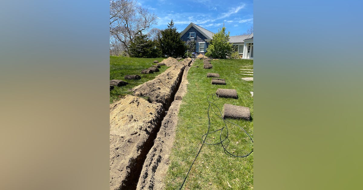
Supply and Return Piping Between Main and Carriage Houses
We buried the supply and return pipes in a two-foot-deep trench with a tracer wire above. No need for insulation or deeper burial as we would be running 30% propylene glycol.
Carriage House Mechanical Room
We suggested erecting a strut framework that was only connected to the existing concrete floor that didn’t touch the walls or ceiling of the mechanical room. Getting all the new mechanical equipment into this tiny mechanical room would require a lot of ingenuity.
We first removed the indirect tank and storage boxes to get a sense of how much room we had to work with. In a typical mechanical room, there is enough wall space to comfortably lay out all the fittings and circulators and appurtenances so that installation and service is straightforward. (The circulators are Goulds E-SV vertical pumps with Goulds Aquavar VFD controls.) But we did not have the wall space in this tiny room. Additionally, because of time constraints, we would have to press all our fittings, which ranged from ½” to 2-1/2” copper. This meant that we had to be very careful about the sequence in which we pressed the fittings, and also how to support the pipe and fittings so that they didn’t lose their alignment during the pressing process.
We set up supply and return risers so that we could make use of the upper part of the mechanical room for the air separator and injection point for the outside fluid cooler and tees for the heat pump and then drop down into the two loop pumps. This would permit us to still get into the back corner of the mech room to service the existing boiler.
Before we installed the two loop pumps on their inertial pads, we re-installed the indirect tank. Then we slid in the two loop pumps. That was our only compromise—when that tank failed we would have to lift the old tank over the loop pump to get it out of the room.
During assembly of all this piping we only used one slip coupling. We had been pressing as we assembled and finally painted ourselves into a corner, and we could not get the press tool in place to get the last joint. In the end we just cut out a large sub-assembly, pressed the last
Because of our upsizing of pipe size, we were able to go from two 10 hp circulators to two 5 hp circulators. The variable speed drives worked well in chasing their pressure target. The system pressure would go up or down depending on how many heat pumps were calling and the pumps would speed up or slow down accordingly. The two drives communicated with a lead-lag arrangement as well.
We filled the system with water first and were so happy to have no leaks. Then we ran the system successfully for the summer before adding glycol for freeze protection.
Happy Homeowner
The system has been working very smoothly since our rescue operation. It is quiet and chilly in the main house (cooling set to 66 F). The new loop pumps can’t be heard in the upstairs bedrooms of the carriage house. The dry cooler is working well to handle the entire cooling load. Another successful rescue project!