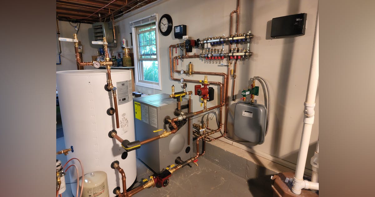
Hover over main image for caption information.
A typical oil fired forced hot water heating system, installed in 1980 was ready for replacement. The original boiler room equipment was removed, which consisted of a boiler with tankless DHW coil and oil burner, the oil tank, three zone valves for copper fin tube convectors, a circulator, one zone valve for a basement fan coil unit heater, zone controls and an expansion tank.
Nothing surprising, just a typical hydronic heating system built in the Northeast and Midwest in the ’60s, ’70s, and ’80s in the United States, of which there are hundreds of thousands still in operation today.
Not only was the boiler room equipment replaced with new updated components but the entire control strategy has been rearranged from intermittent to continuous circulation. Rather than injecting high water temperature intermittently into the system, we are now modulating the water temperature based on room temperature and/or outdoor temperature set point while keeping the circulator running continuously.
The Control Strategy
The rest of the rooms still have the option to close zone valves occasionally based on their settings and occupation. As an alternative, flow meters at the manifold can be fine-tuned to eliminate zone T-Stats and power heads (however, that degree of fine control is not for the average homeowner).
The non-electric room temperature control is an inexpensive control strategy since no expensive electronic reset controls are required. All-in-all, a very cost effective control strategy that provides a simple and reliable building temperature control that will last for many years to come.
The building is being offered the precise amount of BTU’s at any given outdoor or indoor condition, regardless of external or internal heat gains due to solar gain or people.
Keep in mind the most ideal way of controlling a hydronic system is keeping the water moving continuously, fine tuning the water temperature to the building under any condition to supply just the right amount of BTU’s to satisfy the instantaneous heat loss to the building.
High Efficiency
The key link between the heat source and the distribution manifold must be a three way mixing or diverting valve. The advantage of a diverting valve is the option of using non-electric low cost controls. However, if electric controls are desired, you still have the option to do so with a diverting valve. Room temperature feedback from the highest heat loss area of the building is mandatory in
The final component replacement for our system was a double wall polyethylene/sheet metal oil tank with a 275 gallon holding capacity. A safe, clean and space saving solution.
Proper Distribution
Due to a former kitchen remodeling project, a large section of the existing baseboard radiation was removed resulting in insufficient BTU output in the kitchen and the adjacent dining room.
Dramatically improved heating comfort will be realized next winter with a significant fuel reduction. With fuel prices going through the roof, this revamp is a blessing in disguise.
Additional fuel savings will be realized with the use of temperature setback thermostats and master controls.
Compare and Contrast
A typical hydronic heating system from Europe, where forced-air systems are (virtually) unknown, uses constant circulation. Advantages include:
- Significant fuel savings
- Increased heating comfort
- Increased electrical power reduction by eliminating multiple zone circulators and using a single, power-saving, low-wattage circulator with zone valve and flow meter adjustments
- A “perfect marriage” in combination with heat pumps, electric boilers, solar systems and wood-fired boilers
- Small, constant BTU draw at the heat source eleminates problems related to on-off high temperature water distribution systems
- Low water temperature heat sources are now becoming super-efficient hydronic systems
System Components Used in This Installation
Model Vito Rond, 100 model VR 1-22, 80 MBH Output
With Riello oil burner F3, Series 40
VIESMANN DHW TANK:
Model Vito Cell Stainless Steel 300 – V, 42 Gallon Capacity
ROTH DOUBLE WALL OIL TANK
Tank Model DWT 1000L, 275 Gallon Capacity
UPONOR RADIANT HEATING PANELS
QuikTrak Aluminum/Plywood Panels, plus 5/16″ Oxygen Barrier Pex Tubing
VIEGA DISTRIBUTION STATION
Model # 12152 Enhanced Mixing Station for (10) Circuits
VIEGA FITTINGS
Copper ProPress 1/2″, 3/4″, and 1″ fittings
ZILMET EXPANSION TANK
Model ZFT 18 R
OVENTROP NON-ELECTRIC MIXING/DIVERTING VALVE CONTROL #113 02 08
Model 101 22 97 Wall Mounted T-Stat with 33ft Capillary and Valve Actuator
VIEGA ELECTRONIC OUTDOOR RESET CONTROL
(OPTIONAL) PRORADIANT BASIC HEATING
OR
(OPTIONAL) VITOTRONIC 100 CONTROLLER #7834 238
VIEGA/TACO 4-ZONE CONTROL #18060 FOR 24V POWERHEADS AND
FAN COIL UNIT
VIEGA 24V ZONE VALVE POWERHEADS FOR MANIFOLD MOUNTING
Part #15069
GRUNDFOS CIRCULATORS
Mixing Station Modulating Circulator # 99287244 ALPHA2
Fan Coil Unit Circulator # UPS 15 – 58 three speed
DHW Tank Circulator Model # UPS 15 – 58 three speed
AMTROL DHW TANK EXPANSION TANK MODEL # ST5
MILWAUKEE FITTING PRESS TOOL MODEL #2773-20
CALEFFI BOILER FILL AND BACKFLOW PREVENTOR MODEL #573
HYDRO-NODE EXPANSION TANK MOUNTING BRACKET MODEL HN-2
CALEFFI DHW TEMPERING VALVE MODEL #521
